This integration guide describes the configuration steps required for Fonolo Voice Call-Backs (VCB) to integrate with Avaya IP Office over Direct SIP. Fonolo VCB is a cloud-based service that works to save callers from having to hold in a queue for an agent. VCB calls the caller back and connects them with a live call center agent when one becomes available.
Interoperability Between Fonolo and Avaya IP Office
The VCB application is hosted in a cloud environment by Fonolo. SIP trunks are used to connect the VCB application with IP Office. Compatible configurations with Fonolo include Avaya IP Office, either on IP500v2 chassis or an Avaya primary Linux Server, Avaya Voicemail Pro (VMPro), or Avaya Contact Center Select for call center functionality.
In this document’s example configuration, VCB is integrated with Avaya IP Office 9.1 on IP500v2 chassis with Voicemail Pro used to supply call center functionality.
The Caller’s Journey Through IP Office with VMPro with Fonolo
The following steps outline the caller’s journey through an IP Office call center that is offering Fonolo VCB.
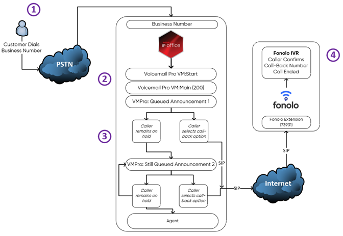
- The caller calls into the IP Office call center.
- The caller navigates the IP Office Voicemail Pro Start Module, and then requests an agent from the given options.
- The caller is sent to a Main Hunt Group within IP Office, where they either opt in to receive a call-back or continue to wait on hold. If they choose to remain on hold, they eventually hear a second announcement, offering a call-back again.
- If they opt to get a call-back, the caller is transferred to a Fonolo Extension (73931 for this example). To verify the number that will receive the call-back, we read back the caller’s phone number. Alternatively, the caller can press DTMF 2 to enter a different number to get a call-back on. The caller can also be offered other options, such as the ability to schedule their call-back for a later date or time.
- After the caller verifies their number, the call ends.
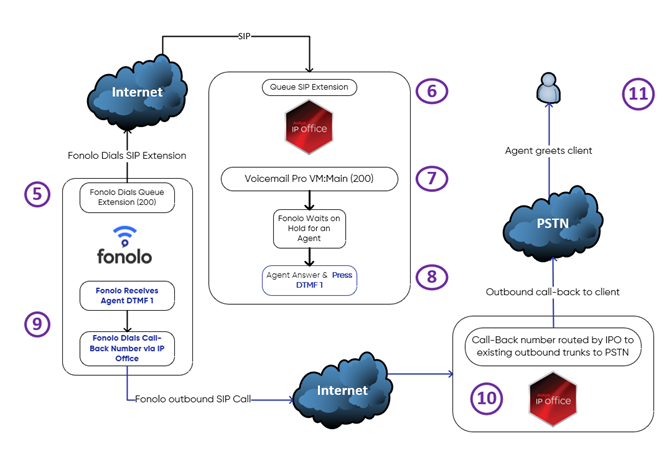
Figure 2. Fonolo placeholder call to the queue and call-back to the caller after connecting with a live agent - Fonolo’s automated system either dials into the IP Office queue SIP extension (200, for this example) immediately or waits until the scheduled time to start waiting for an agent on behalf of the caller.
- The Fonolo placeholder call traverses the Main Hunt Group.
- The call is placed on hold for the next available agent.
- When the agent becomes available, their phone rings. When they answer, they hear a repeating Fonolo whisper telling them that there is a caller requesting a call-back, and to press DTMF 1 to connect to them now. The message repeats indefinitely until the agent presses 1.
- After Fonolo receives the DTMF 1 from the agent, we send a SIP invite to the call-back number (including the country code) over the internet using the IP Office’s trunk.
- The IP Office sees the 11-digit incoming SIP call and forwards it through the existing outbound trunks to the PSTN to connect with the caller.
- The caller picks up, and the agent is bridged with them so that the agent can greet them directly.
Reference Configuration
Fonolo IPO Demo is a simulated company that is used in this example to set up a call-back service for one of its queue flows in IP Office, connecting it to Fonolo.
- The Fonolo Demo IP Office sample queue extension is 200.
- The Fonolo Demo IP Office VMPro start point is Start.
- The Fonolo extension callers will be transferred from IP Office to is 73931.
- Fonolo will dial out to the Caller through IP Office using SIP.
IP Office Configuration Steps
Configuration using IP Office in this section is done with Avaya IP Office Manager, on an IPO500V2 control unit. It is assumed that a working system is already in place with the necessary licensing and locale configuration.
System Configuration
- To launch the Manager application, from a PC running the IP Office Manager application, select Start > Programs > IP Office > Manager.
- Select the proper IP Office system and log in.
- In the IP Offices pane, select Fonolo IPO Demo > System > Fonolo IPO Demo. The IP Office system opens, named, in this case, Fonolo IPO Demo.
- Select the LAN1 tab.
- Note the configured IP address in the LAN settings sub-tab. In this example, the IP is 192.168.2.64. This IP Address is needed during VCB configuration.
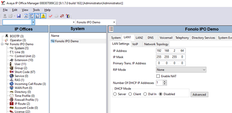
Figure 3. Fonolo IPO Demo LAN1 LAN settings - Select the VoIP sub-tab.
- Make sure that the SIP Trunks Enable and SIP Registrar Enable checkboxes are selected.
Create SIP Lines
Two SIP lines must be created, one line for outgoing calls (IP Office to Fonolo) and one line for incoming calls (Fonolo to IP Office).
Fonolo uses six SIP gateways. Two (64.190.42.33 and 64.190.42.34) are used to send calls from the phone system to Fonolo for the opt-in step. The remaining four gateways (64.190.42.35, 64.190.42.36, 64.190.42.37, and 64.190.42.38) are used for calls from the Fonolo system to your system; for both the call to the queue extension, and for the outbound call to the caller.
Create outgoing SIP lines to the Fonolo trunk
First, we must create the SIP line from the IP Office to Fonolo for outgoing calls.
- Go to System > Line (right-click) > New > SIP Line. In this example, line 17 is used to connect to Fonolo.
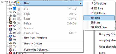
Figure 4. Adding a new SIP line Figure 5 shows the configuration of the SIP line in the SIP line window that opens.
- Enter the following information in the SIP Line tab. Leave any fields not mentioned as default.
Field Value Line Number Enter the SIP line number. In this example, we are using line 17. ITSP Domain Name (Optional) Configure the domain name of the ICR. Description (Optional) Enter a description of the SIP line. 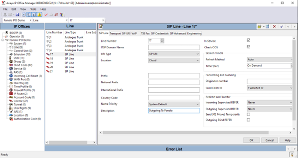
Figure 5. SIP line outbound configuration - In the Transport tab, enter the IP address of the ICR in the ITSP Proxy Address field. In this example, 64.190.42.33 and 64.190.42.34 were configured. We recommend configuring two servers for outgoing calls, for load balancing and active redundancy purposes.
- (Optional) Enter up to three more IP addresses, separated by a comma or space, in the ITSP Proxy Address field.
- In the Network Configuration section, select UDP from the drop-down menu of the Layer 4 Protocol field. Leave the other fields as default.
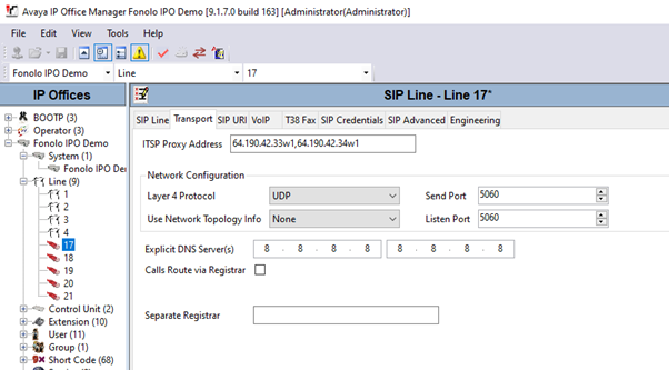
Figure 6. SIP line outbound Transport tab configuration - Go to the SIP URI tab and select Add. The Edit URI pane opens
- Enter the following settings. Leave any fields not mentioned as default.
Field Value Local URI Auto Contact Auto Display Name Auto Incoming Group Select an available group number. In this example, we are using line 18. Outgoing Group Select an available group number. In this example, we are using line 18. Max Sessions Choose the maximum number of sessions for the SIP line. In this example, we are using a max of 10. - Select OK to save the URI settings.
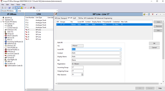
Figure 7. SIP line outbound SIP URI tab configuration - Go to the VoIP tab and make sure that RFC2833 or RFC4733 is selected in the DTMF Support field. Leave the other fields as default.
Default values were kept for the fields in the SIP Credentials, SIP Advanced, and Engineering tabs.
- Select OK to complete the configuration of the new outbound SIP line.
Create inbound SIP lines from the Fonolo SIP trunk
The process of creating an inbound SIP line from Fonolo to IP Office is much like creating an outbound line.
- Go to System > Line (right click) > New > SIP Line. In this example, line 18 is used to connect to the ICR.
- Enter the following information in the SIP Line Leave any fields not mentioned as default.
Field Value Line Number Enter the SIP line number. In this example, we are using line 18. ITSP Domain Name (Optional) Configure the domain name of the ICR. Description (Optional) Enter a description of the SIP line. 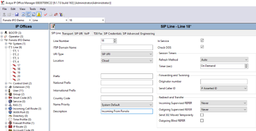
Figure 8. SIP line inbound SIP Line tab configuration - In the Transport tab, enter the IP address of the ICR in the ITSP Proxy Address In this example, 64.190.42.35w1, 64.190.42.36w1, 64.190.42.37w1, and 64.190.42.38w1 were configured. ICR requires the use of four servers to place calls to the IPO.
- (Optional) Enter up to three more IP addresses, separated by a comma or space, in the ITSP Proxy Address field.
- In the Network Configuration section, select UDP from the drop-down menu of the Layer 4 Protocol field. Leave the other fields as default.
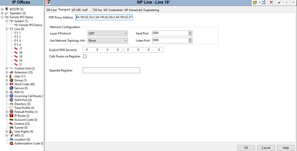
Figure 9. SIP line inbound Transport tab configuration - Go to the SIP URI tab and select Add. The Edit URI pane opens.
- Enter the following settings. Leave any fields not mentioned as default.
Field Value Line Number Enter the SIP line number. In this example, we are using line 18. ITSP Domain Name (Optional) Configure the domain name of the ICR. Description (Optional) Enter a description of the SIP line. - Select OK to save the URI settings.
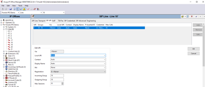
Figure 10. SIP line inbound SIP URI tab configuration - Go to the VoIP tab and make sure that RFC2833 or RFC4733 is selected in the DTMF Support field. Leave the other fields as default.
- In the Media Security field, select Disabled. Leave the other fields as default.
Default values were kept for the fields in the SIP Credentials, SIP Advanced, and Engineering tabs.
- Select OK to complete the configuration of the new inbound SIP line.
Define the Incoming Call Route
To configure the incoming call route:
- Go to Fonolo IPO Demo > Incoming Call Route (right-click) > New.
- In the Standard tab of the new window, enter the following settings. Leave the other fields as default.
Field Value Bearer Capability Any Voice Line Group ID Enter the SIP line that you created in the previous section. In this example, we are using line 18. - Go to the Destinations tab and, under the Destination column, enter a period (.). Leave the other fields as default.
- Select OK to save your changes.
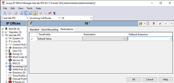
Figure 11. New call route Destinations tab configuration
Create a Short Code for Outgoing Calls to Fonolo
A short code needs to be configured in IP Office to route calls to Fonolo VCB.
-
- Go to Fonolo IPO Demo (or your own IP Office company name) > Short Codes (right-click) > New.
- Enter the following settings:
Field Value Code Enter a name for the short code. In this example, the code is named 73N. Feature Select Dial. Telephone Number Enter a period (.). Line Group ID Select the SIP line group that was created for sending calls to Fonolo. In this example, we enter line 17. 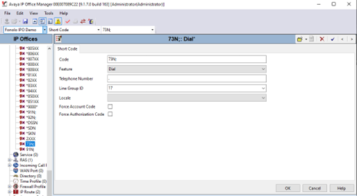
Figure 12. Creating a new short code - Select OK to save the short code.
Save and Update IP Office
Once all the configurations are complete, they must be saved on the IP Office system.
- Select Save, shown in Figure 13, to save your changes. Select OK when prompted to confirm.
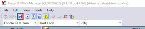
Figure 13. IP Office Save button
Voicemail Pro Configuration Steps
In this example, Fonolo VCB is integrated with Avaya IP Office 9.1 on IP5000v2 chassis with Voicemail Pro used as the contact center implementation to provide call center functionality. The following steps go over a sample configuration setup of an IVR, queueing, and call-back offer messaging using VMPro.
Create a Hunt Group and Assign Agents
For an active call center, there should already be hunt groups configured, and those same groups can be used for this setup.
To create a new hunt group:
- Log into the IP Office control unit with valid credentials.
- In the left pane, go to Group (right-click) > New.
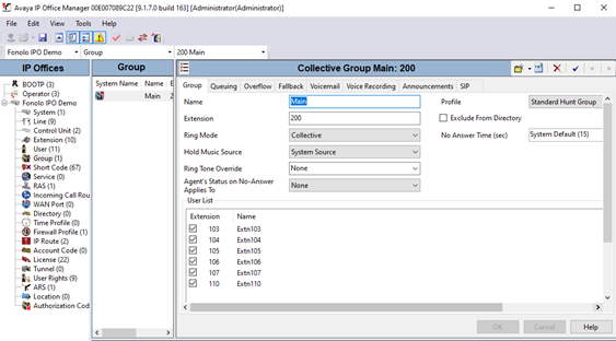
In this example, we are using the Main hunt group as the queue. Figure 14 shows a hunt group setup under the name Main with extension 200. Six agents are added to the hunt group, with a Collective Ring Mode.
- Go to the Voicemail tab and set the Voicemail Type to Voicemail Lite/Pro.
- In the Voicemail IP Address field, enter the VMPro IP address. In this example, we are using 192.168.2.88.
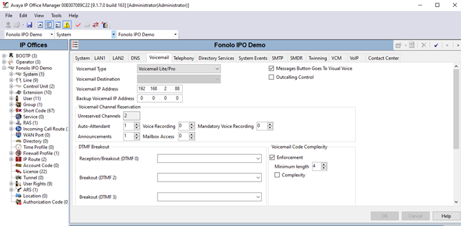
Figure 15. Hunt group Voicemail tab configuration
Enable Queueing
- Go to the Queueing tab and make sure that the Queueing On checkbox is selected.
- Set the Queue Length to No Limit.
- Set the Queue Type to Assign Call on Agent Answer.
Enable Announcements
- Go to the Announcements tab and make sure that the Announcements On checkbox is selected.
- Enter the following settings:
Field Value Wait before 1st announcement (sec) 5 Flag call as answered ✓ Post announcement tone Music on Hold 2nd announcement ✓ Wait before 2nd announcement (sec) 10 Repeat last announcement ✓ Wait before repeat (sec) 10 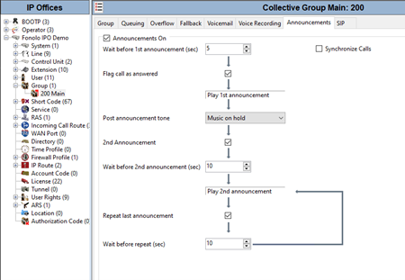
Figure 16. Hunt group Announcements tab configuration
Configure the Voicemail Pro Server
You can access the Voicemail Pro (VMPro) server configuration and Flows through the VMPro client.
Log into VMPro by entering the IP address of the voicemail server and valid credentials.
Create Welcome Call Flow
- In the left pane, create a start point by selecting Module (right-click) > Add. The Adding a new start point dialog opens.
- Enter a name for the start point and then select OK.
- Add a menu and transfer step, outlined in Figure 17.This module creates a welcome menu that gives the caller the option to speak with customer service after pressing DTMF 1, which transfers them to the Main Group (extension 200) to wait for an agent.
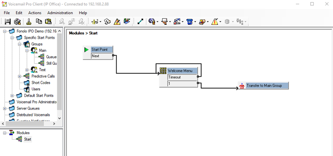
Figure 17. Example module configuration - Double-click the Menu module to access its properties. In this example, we have named it Welcome Menu.
- Go to the Entry Prompts tab and select Add (+). The Wave Editor dialog opens.
A welcome greeting prompt should be uploaded to play when a caller is transferred to the main menu. - Select a welcome prompt file, or record the desired prompt, and then select Close.
Next, we need to assign the Touch Tones to listen for from the caller after they hear the welcome prompt.
- Go to the Touch Tones tab and select the 1 checkbox.
- Select the Timeout checkbox and set the value to 5 seconds. Select OK to close the properties dialog.
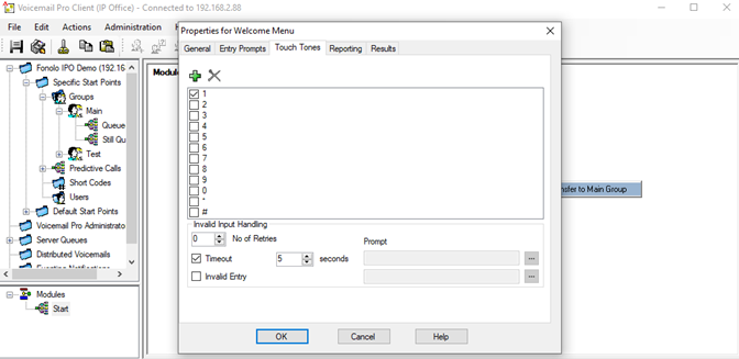
Figure 18. Welcome menu Touch Tones tab configuration
Next, we must assign the hunt group that the caller will be transferred to after they make a queue selection. In this example, there is a single option with a 5 second no entry timeout.
- Double-click the Transfer module. The Properties dialog for the module opens.
- Go to the Specific tab and enter the hunt group extension in the Destination field. In this example, we direct the extension 200 to the Main hunt group.
- Set the Source of transfer (displayed on phone) to $CLI to properly pass the original caller ID information to the queue and agent.
- Select OK to close the Properties dialog and save your changes.
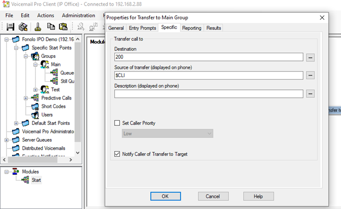
Figure 19. Main group properties specific tab configuration
Create a Queued Point for the Main Hunt Group (Announcement 1)
Now that we have a caller directed to the Start menu, they make a queue selection (pressing DTMF 1) and are transferred to the Main hunt group, extension 200. If agents are unavailable, the caller is queued and starts to follow the hunt group queue settings defined in the previous section.
We need to modify the specific start points for the Main hunt group, the Queued, and the Still Queued group modules in VMPro.
- In the left pane, go to Specific Start Points > Groups > Main > Queued (right-click) > Edit.
- Add a Menu module and a Transfer step as shown in Figure 20.
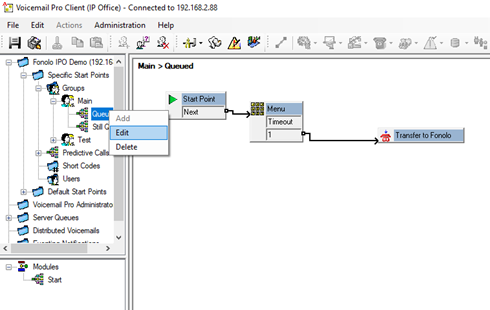
Figure 20. Queued module configuration - Go to Menu (right-click) > Properties > Entry Prompts > Add (+). A call-back offer message should be uploaded to play when the caller is sent to the Queued module.
- Select a call-back offer message file or record the desired prompt and then select Close.
Next, we must define the keys that will be listened for after the offer message is played. In this example, we are using DTMF 1 as the confirmation key for getting a call-back.
- Go to the Touch Tones tab and select the 1 checkbox.
- Select the Timeout checkbox and set the value to 5 seconds. Select OK to close the menu properties dialog.
When the caller presses DTMF 1 to get a call-back, the call must be transferred over to the Fonolo extension to the Fonolo Cloud through the SIP line created earlier.
- Right-click the Transfer module and select Properties.
- Go to the Specific tab and enter the given Fonolo Destination extension. In this example, the Fonolo extension is 73931.
- In the Source of transfer field, enter $CID $CLI.
- Select OK to save your changes.
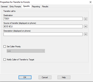
Figure 21. Fonolo transfer specific tab configuration
Create a Still Queued Point for the Main Hunt Group (Announcement 2)
While we have created our first announcement flow, there will be cases where a caller does not opt in the first time a call-back is offered. In these cases, a second announcement, using a Still Queued module, can be used to play another call-back offer. This offer be repeated until an agent picks up, letting callers who decide to opt in later do so without needing to hang up and call back in.
We will follow the same steps to edit the Still Queued start point as we have for the Queued start point above.
- On the left pane, go to Specific Start Points > Groups > Main > Still Queued (right-click) > Edit.
- Add a Menu module and a Transfer step.
- Go to Menu (right-click) > Properties > Entry Prompts > Add (+). A call-back offer message should be uploaded to play when the caller is sent to the Still Queued module. The same offer message from the previous section will work.
- Select a call-back offer message file or record the desired prompt and then select Close.
Next, we must define the keys that will be listened for after the offer message is played. In this example, we are using DTMF 1 as the confirmation key for getting a call-back.
- Go to the Touch Tones tab and select the 1 checkbox.
- Select the Timeout checkbox and set the value to 5 seconds. Select OK to close the menu properties dialog.
When the caller presses DTMF 1 to get a call-back, the call must be transferred over to the Fonolo extension to the Fonolo Cloud through the SIP line created earlier.
- Right-click the Transfer Module and select Properties.
- Go to the Specific tab and enter the given Fonolo Destination extension. In this example, the Fonolo extension is 73931.
- In the Source of transfer field, enter $CID $CLI.
- Select OK to save your changes.
Fonolo Portal Configuration Steps
Fonolo will configure the Fonolo Portal to handle the callers that are transferred over from IP Office to Fonolo, where we confirm their details for the call-back. Go to the Fonolo Help Site for additional guides and information.
To do this configuration in the Fonolo Portal, you must have a Portal user account with either the Standard or Account Manager roles. For more assistance, contact us at our support line.
Create a SIP Trunk Group between Fonolo and IP Office
- In the Fonolo Portal, go to Telco > SIP Trunks > Add New SIP Trunk Group.
- Enter a name for the SIP trunk group and then select Save Changes.
- On the SIP Trunk Groups page, select the newly created group and go to the Members tab.
- Select Add New Member. The Add New SIP Trunk dialog opens.
- Enter the following settings:
Field Value SIP Label Enter a name for the SIP trunk, shown only in the Fonolo Portal.
In this example, we name it Fonolo IPO Demo Trunk.SIP URL Enter the IP address of the IP Office SIP peer.
The IP address must be formatted as a fully qualified URL, defining the protocol and SIP port.DTMF Mode Select the DTMF mode that is used to send DTMF tones.
The recommended mode is RFC 2833.Identity Header Choose whether to include an identity header (and, if so, what type of header). Codec Support Choose an audio codec to use. Priority Enter the priority level of the SIP trunk.
The priority is a numeric value that determines failover or load balance when more than one SIP trunk group member is defined. Members with lower priority are used first, while members with equal priority are load balanced.Keepalive Enable a keepalive timer for this host.
Choose whether Fonolo sends regular keep-alive messages using SIP OPTIONS requests. By default, this setting is disabled.Session Timers Choose whether to enable SIP Session Timers (RFC 4028).
By default, this setting is disabled.NAT Support Enable this setting if the SIP trunk is behind a NAT device.
Fonolo can compensate for the unreachable RTP data specified in the SDP body of the INVITE request by using symmetric RTP. - Select Save Trunk.
We must also configure the short code for outbound dialing from IP Office. As an example, the short code to dial outbound (to PSTN) from IP Office is 9N. Therefore, all outbound calls to customer call-back numbers through IP Office must be prefixed with a 9.
To configure this:
- In the Fonolo Portal, go to Telco > Call Routing > Add New Call Routing Profile.
- Enter a name for the profile in the Profile Label field and then click Add New Call Routing Profile to create it.
- Open the call routing profile and enter the digit 9 into the Default Prefix field.
- Select Save Changes.
Create a Target and Assign a Queue Extension
A Target is an entry point into the queue that Fonolo uses to place a call-back and wait on hold on behalf of the caller. While callers are often required to go through the IVR system, Fonolo uses the target to connect directly into a specific queue, bypassing the IVR.
- Go to Manage > Targets > Add New Target.
- Enter a name for the target in the Target Label field.
- In the Dial Method field, select Dial as a SIP Extension.
- In the Extension field, enter the extension of the relevant skillset in IP Office. In this example, 200 is the Main hunt group extension in IP Office, so we enter 200.
- Select Add New Target to save the Target.
- Open the target settings and go to the Telco Settings tab.
- From the Direct SIP drop-down menu, select the relevant SIP trunk to use for this target.
- Select Save Changes.
Go to Adding a New Target for more information on creating targets.
Create a Call-Back Profile and Assign the Target
A Call-Back Profile is a collection of settings that define the calls that Fonolo receives and places for you. Once a client opts-in for a call-back, the call is transferred to Fonolo, where we collect any necessary information, end the call, and then place a new call into to your ACD.
- In the Fonolo Portal, go to Manage > Call-Back Profiles > Add New Profile.
- Enter the following settings to configure the profile:
Field Value Profile SID (Read-only) Shows the assigned system ID (SID) of the call-back profile. Profile Label Enter a name for the call-back profile. This name will appear in reports and statistics generated by the Fonolo Portal. Geo. Whitelist Select an allow list of countries and regions that Fonolo is allowed to place calls within.
Go to Localization for more information on creating geographic whitelists.Channel Choose the type of call-back the profile is attached to:
- In-Call Rescue (Voice call-backs)
- API Access (Programmable call-backs)
- Responsive Web Rescue (Web call-backs)
This field is configured upon call-back profile creation and cannot be changed afterwards.Language Choose the language the queue will handle.
This field is configured upon call-back profile creation and cannot be changed afterwards.Customer CID Number Enter the phone number that is shown to the caller when they receive their call-back from Fonolo.
We recommend entering your service center phone number, to help identify you to the caller.Customer CID Name Enter the name that is shown to the caller when they receive their call-back from Fonolo.
We recommend entering your company name, to help identify you to the caller.Agent CID Number Enter the phone number that is shown to your agents when they receive the placeholder call from Fonolo.
The macro{{$client_number}}will show the caller’s call-back number as the Agent CID Number.Agent CID Name Enter the name that is shown to your agents when they receive the placeholder call from Fonolo.
We recommend entering “Fonolo”, to tell your agents that this is a call-back and not a real caller (yet!). - Select Add New Call-Back Profile to create your new profile.
- Open the call-back profile settings page and go to the Call Options tab.
- Select the target you created in the previous section and then select Add Option.
- Select Save Changes.
This associates the target CDN with the new call-back profile. Multiple call options can be associated with a single call-back profile. For example, you can have one target for each skill that call-backs are being offered on in the same call-back profile, and they will all use the exact same call-back profile settings.
- Go to the Telco Settings tab of the call-back profile.
- Enable the Direct SIP radio button under both the Client Call-Back Method and In-Call Rescue Transfers headings.
- Select the SIP trunk group you created in a previous section under both the Client Call-Back Method and In-Call Rescue Transfers headings.
- Select Save Changes.
Go to Add A New Call-Back Profile, How to Configure a Call-Back Profile > Settings, and How to Configure a Call-Back Profile > Call Options for more information on configuring call-back profiles.
Assign the Fonolo Extension for Opt-In Transfer
- Go to Manage > Call-Back Profiles.
- Select the Call Options option on the new call-back profile. The ICR Settings dialog opens.
- Enter the inbound extensions to use for each pertinent IP Office hunt group.
These are the extensions to transfer calls to, through the ICR system, when a caller opts in for a call-back.
Go to How to Configure a Call-Back Profile > Call Options for more information on configuring call-back profile options.